Peerless Kcd2 Switch Diagram

Switching status indicator yellow led.
Kcd2 switch diagram. The top countries of supplier is united states from. Clips onto standard 35 mm rail to din en 50 022. Short circuit proof electronic output.
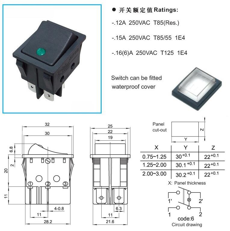
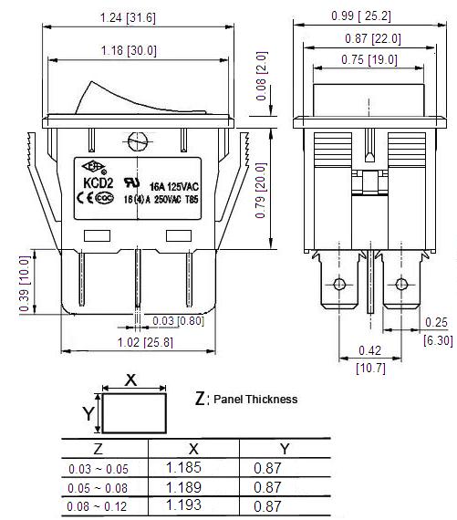
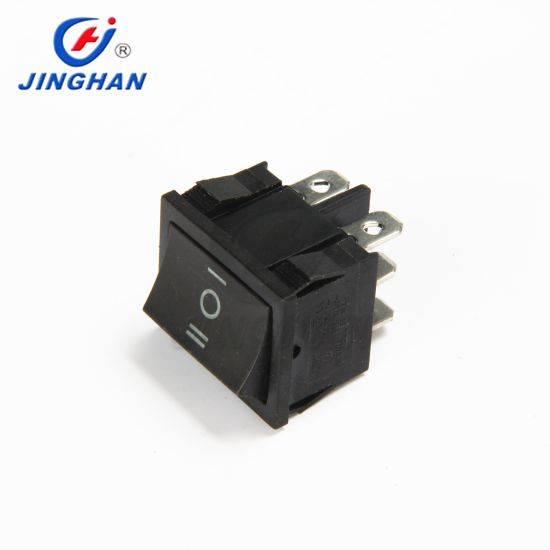
Line fault detection lfd housing width 12 5 mm. Name kcd2 dpdt 6 pins rocker switch product type kcd2 22 ca2a b w max rating current 16 4 a 250v ac contact resistance 50mω insulation resistance 1000mω dielectric strength 1500v ac 1min. Rocker switches are commonly used to directly power a device.
All product related documents such as certificates declarations. Dc 24 v supply voltage. Available termination options include smt pcb pins solder lugs screw.
They are available in many shapes sizes and colors with both standard and custom symbols available on the actuator. This is a video explanation of how to wire the very common kcd2 illuminated rocker switch. Switch amplifier kcd2 sr ex2 kcd2 sr ex2.
Ask an expert. Standard interface for prevention of signal transmission errors. The lead breakage monitoring can be disconnected by bridging terminals 1 and 3.
Rocker switch illumination may be controlled on a separate circuit or be dependent on switch position based on what series is chosen. Relay output with 1 pole yellow led indicates switching state. All product related documents such as certificates declarations of conformity etc which were issued prior to the.


