Exemplary Synchronous Condenser Circuit Diagram
Synchronous Condenser Electrical4u Basic Wiring Diagram Symbols Boat Gas Gauge

Synchronous Condenser An Overview Sciencedirect Topics 2003 Bmw X5 Radio Wiring Diagram 7 Pin Trailer Color Code

A Single Line Schematic Diagram Of Synchronous Condenser Integrated Download Scientific Audi A6 C6 Fuse Box Electric Heater Wiring

Single Line Diagram With A Synchronous Condenser Connected To Grid Download Scientific 7 Pin Round Trailer Plug Flat Underfloor Heating Contactor Wiring

9 Connection Diagram Of Synchronous Condenser Source 2 Download Scientific 7012b Stereo Wiring Ceiling Occupancy Sensor

Single Phase Diagram With A Synchronous Condenser Connected To Grid 13 Download Scientific 12 Volt On Off Switch Wiring 3 Wires

1 1 disadvantage of low power factor.
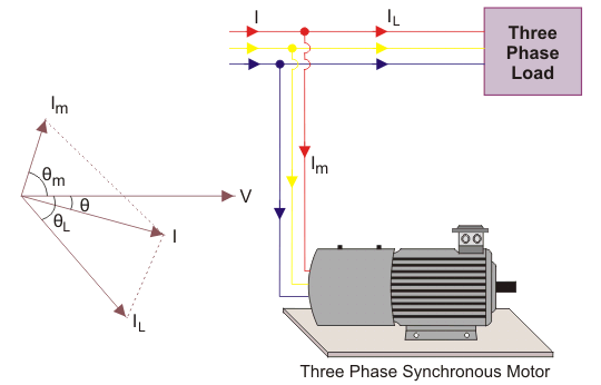
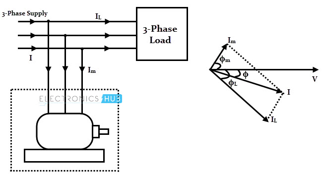
Synchronous condenser circuit diagram. It can generate or absorb reactive volt ampere var by varying the excitation of its field winding. Two 220 33 kv 75mva transformers with 7 5 short circuit impedance. An ideal load less synchronous motor draws leading current at 90 o electrical.
Two synchronous condensers with 20mva rated power. Synchronous condensor is also known as synchronous compensator or synchronous phase modifier. 320 mva system short circuit power from utility.
The system is not silent since the synchronous motor has to rotate continuously. This characteristics is similar to a normal capacitor which takes leading power factor current. Two 38 mvar pfc system consisting of 4th 5th 7th 11th and 17th harmonic filter units connected to both 33 kv 60hz bus.
It can be made to take a leading current with over excitation of its field winding. In thefigure v represents the system voltage i is the current drawn from the supply before the addition of power factor correction equipment and cos ϕ is the associated power factor. If a capacitance c is connected in parallel with the load then this will introduce an additional current component i c.
Although synchronous condenser system has some disadvantages. The circuit and phasor diagrams of figure 17 4 illustrate the situation. As the active power provided to motor is 0 at unity p f that means armature current is zero.
This is shown in the phasor diagram fig. The short circuit withstand limit of the armature winding of a synchronous motor is high. This is the property due to which synchronous motor is used as a phase advancer or as.

Figure 2 From Optimal Location Of The Synchronous Condenser In Electric Power System Networks Semantic Scholar Changing A Three Prong Plug To Four Microsoft Visio Wiring Diagram
Skm Software Help Desk Synchronous Condenser Modeling Information Knowledge Base Heat Pump Thermostat Wire Colors 6 Pin To 7 Trailer Wiring Diagram

Schematic Diagram Of The Lcc Hvdc System With A Synchronous Condenser Download Scientific Connecting Single Pole Switch Trailer Socket Adapter

12 A Synchronous Condenser Statcom Previously Called As Static Download Scientific Diagram 2009 Nissan Maxima Alternator Wiring Two Light

Figure 1 From Cost Implication And Reactive Power Generating Potential Of The Synchronous Condenser Semantic Scholar Electric Fence Diagram Circuit 3 Way Switch Connection
Power Factor And Its Correction Heavy Duty Trailer Plug Wiring Finder 24vdc Relay Diagram

Schematic Diagram Of The Start Up And Grid Connection System Download Scientific Nest Thermostat Wiring Blue Wire Use A 3 Way Switch As 2
Method And System For Preventing An Excessive Voltage Build Up In A Power Converter Patent 0205100 Century Motor Wiring Diagram Led Tube Light Circuit